This document is the high-level user manual and description of the LATISS Instrument. As details are filled out, it is expected that the document may split into a LATISS operations manual and a separate technical manual.
1 The LSST Auxiliary Telescope and LATISS
The Auxiliary Telescope (AuxTel) is a 1.2m telescope with LATISS is responsible for providing atmospheric calibration data for the main LSST telescope. The purpose of this handbook is to act as a reference guide to an operator and /or technician who has some knowledge of LSST systems, but may not be an expert in operating the AuxTel or LATISS.
Table Table 1 gives a brief overview of the optical characteristics of the telescope and instrument
| Mirror Diameter | 1.2 m |
| Focal Length | 21.6 m |
| f/# | 18 |
| Plate Scale | 0.1”/pix |
| Pixel Size | 10x10 um |
| CCD Size | 4K x 4K |
| No. of Filters | 3+1 Blank |
| No. of Dispersers | 3+1 Blank |
Two instruments are generally mounted on the AuxTel. Nasmyth port 1 contains a high-speed CMOS camera used for alignment testing. Nasmyth port 2 contains LATISS. Although this is the standard configuration, the instruments can be mounted on either port.
There are a large number of subsystems present within the framework of AuxTel, which can be confusing. We detail below a few useful acronyms and the subsystems to which they relate.
The most important concept to understand is that the LATISS instrument is composed of two components, the top-level documentation for each is found at the LATISS top-level Docushare link:
- AuxTel Spectrograph instrument(often referred to as the ATS). This consists primarily of the filter and disperser wheels, and was built by Astronomical Consulting and Equipment (ACE).
- Auxiliary Telescope Spectrograph Sensor and Readout System (ATSSRS), which refers to the cryogenic dewar and electronics that house and readout the CCD imager. The ATSSRS can be identified as the bronze colored dewar attached to the black housing of the ATS. It was built by Harvard University.
TODO! Need to probably define CCS/OCS/TCS/SAL/DAQ/DM
2 Auxiliary Telescope Spectrograph Overview
See the Document-30997 for a description of the Spectrograph Instrument.
3 Auxiliary Telescope Spectrograph Sensor and Readout System Overview
3.1 System Overview
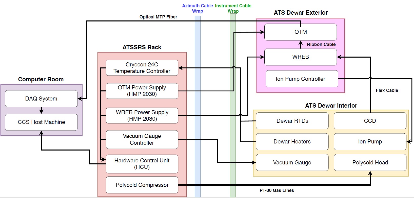
Figure 1 Caption text.
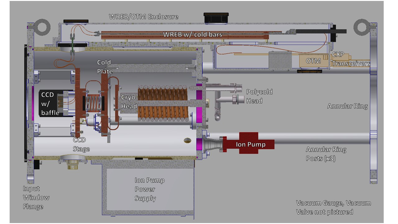
Figure 2 A cut through of the ATSSRS internals.
3.2 ATSSRS Electronics Overview
The ATSSRS consists of a single LSST ITL Type A chip (Serial Number 068), which is read out by a standard LSST Wavefront Raft Electronics Board (WREB). The signal is digitized by a standard LSST Optical Transition Module (OTM) and sent via an MTP data fiber to the the DAQ located in the summit server room. The ATSSRS electronics are controlled by a Hardware Control Unit (HCU).
Some unique aspects of the ATSSRS compared to a standard LSST readout chain include:
- Long active flex cables from the CCD’s JST connectors to the dewar feedthrough
- Ribbon cables (rather than flex) from the dewar feedthrough to the WREB Nano-D connectors
- Non-LSST power supplies (HMP 2030, Keithley 6487)
An overview of the off-the-shelf electrical components present in the ATSSRS system is given below:
| Equipment | Part Number | Manufacturer |
|---|---|---|
| WREB/OTM/Fan PSUs | HMP2030.02 | Rohde & Schwarz |
| Back Bias PSU | 6487 | Keithley |
| Hardware Control Unit | UNO-1483G-434AE [1] | Advantech |
| [1] | The HCU requires additional options: SQF-S25M4-128G-S9E, PCM-27D24DI-AE, and 96PSA-A120W19T2 |
3.2.1 ATSSRS Power Supplies
ATSSRS comes from a set of 3 Rohde & Schwarz HMP 2030s (each of which has 3 channels) and a Keithley 6487 Picoammeter/Voltage Source, which has a single voltage source output. The HMP 2030s supply WREB, OTM, and fan power, while the Keithley 6487 supplies the back bias voltage. The main power cable to the WREB is connected to the rack bulkhead-mount socket labeled . The power cable for the WREB also carries OTM power. Table 3 shows the configuration of the ATSSRS power supplies.
| HMP 2030 Unit 1 (Spare - Unit 5) | ||
| Channel 1 | DPHI | |
| Channel 2 | V\(_\mathrm{OD}\) | |
| Channel 3 | V\(_\mathrm{DREB}\) | Digital WREB power |
| HMP 2030 Unit 2 (Spare - Unit 6) | ||
| Channel 1 | clkL | Clock Low (serial?) |
| Channel 2 | clkH | Clock High (serial?) |
| Channel 3 | V\(_\mathrm{Ana}\) | Analog power |
| HMP 2030 Unit 3 (Spare - Unit 4) | ||
| Channel 2 | Fan Power | WREB fan power |
| Channel 3 | Spare | |
| Voltage Source Output | BSS | Back bias |
The power supplies are housed in the ATS rack, on the floor of the AuxTel dome. All channels for the HMP 2030s, with the exception of fan power, are run with sense lines to correct for IR voltage drop across the long cable run to the instrument. Fan power is adjusted by simply adding a small offset to the nominal fan voltage (12V).
The Keithley back bias supply is capable of supplying up to 500V, and is capable of causing damage to the CCD. To limit this risk, a custom voltage limiting circuit constructed from a Zener diode (Vishay Industries Part No. 1N5264B-TAP – 60V 0.5W Zener Diode) and resistors. The circuit (see Figure 3) limits the voltage supplied to the WREB back bias pins to 70V, even if 500V is applied. The circuit has been tested in the laboratory (without the CCD attached) and successfully clamps the output voltage to the CCD at approximately -68V. This is intended as a hardware risk mitigation system, and should not be used during normal operations. There is nominally a software limit that prevents damaging voltages from being requested.
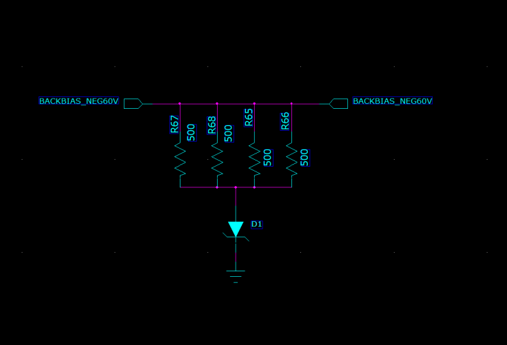
Figure 3 Back bias voltage limiting circuit. The resistors are 500\(\Omega\) 0.25W.
3.2.1.1 HMP 2030 PSUs
The HMP 2030 PSUs are intended to be run under CCS control, and in general should not require manual intervention. The power supplies can be turned on and enabled remotely by CCS. When the power supply is turned on, the screen activates and the “Power” button becomes lit. The channel buttons in the upper right hand corner will glow green when the channel is enabled, and blue when the channel is being manually configured. If the channel is disabled, the backlight will turn off. When output is enabled, the “Output” button in the far upper right corner will be backlit, and will be dark if output is disabled. Note that the channel lights can still be green even when output is disabled, and output can be enabled even if all channels are turned off. In both of these cases, no voltage is supplied to a piece of equipment on that channel. The units additionally have current limits enabled to prevent massive overdraws of current due to, e.g., misconfiguration. Additionally, the HMP 2030s are single quadrant supplies, which means they can only supply a positive voltage across the outputs. This can be side-stepped in hardware (e.g., by connecting device + to PSU - and vice versa), but all voltages requested by software must be positive.
The 6 HMP 2030 channels of Unit 1 and Unit 2 PSUs should be powered on in a specific order – although unlikely, damage to the CCD may occur if this order is not followed. CCS should be used to enable the HMP 2030 outputs to avoid damage to the CCD.
See attached cabling diagram for ATSSRS power supply cable locations. TODO! ADD CABLING DIAGRAM
3.2.1.2 Keithley 6487 Picoammeter/Voltage Source
The Keithley 6487 supplies the back bias voltage to the WREB, which in turn feeds the voltage to the CCD. No manual control of the Keithley should be necessary – all communication should be done via CCS, so that operating limits are not exceeded. The ATSSRS CCD is intended to operate at a back bias voltage of approximately -50V. There is no sense line for the back bias voltage. When back bias is enabled, the blue light labeled will be lit. Note that the output of the Keithley is connected first to a black BUD box, and from there to the BNC cable labeled – this black BUD box contains the voltage limiting circuit to prevent accidental application of more than -70V of back bias. When operating at -50V, the Keithley should display almost 0A running through the system. Any significant current flow through the back bias supply means something has gone wrong.
3.2.1.3 Power Supply Cabling
Cabling for the ATSSRS power supplies is provided, for the most part, by a large white cable procured from SLAC. This cable is in 3 pieces: the first (LCA-16569-A) connects the rack equipment to a bulkhead MS connector (labeled ), the second (no LCA) is a 75’ straight through cable that passes through the various cable wraps, and the third (LCA-16570-B) connects a bulkhead MS connector to the 51-pin WREB and 4-pin OTM connectors.
Fan power is run through a 14-pin MS connector which has three sections: the first from the HMP 2030 power supply to the rack bulkhead plate (labeled ), the second from the rack bulkhead plate to the bulkhead connector on the underside of the WREB enclosure mount, and the final section runs from the bulkhead connector to the thermostat enclosure mounted on the top of the WREB enclosure lid. This final section has disconnects installed, so that the enclosure lid may be removed. Pliers may be useful for separating the disconnects.
3.3 ATSSRS Cryogenics Overview
The ATSSRS cryogenic system consists of a Polycold compressor with 75’ gas lines (0.5” DIA braided steel exterior) feeding a Polycold cold head. There are separate (labeled) supply and return lines that must be correctly connected to the cold head and compressor. The Polycold system uses the PT-30 refrigerant mixture. The Polycold compressor is a simple on-off device, and provides essentially no method for regulating temperature of the system. Before the Polycold can be turned on, the dewar pressure should be below approximately 10\(^{-4}\) Torr. Too much atmosphere in the dewar results in a large thermal load on the Polycold head, which can cause venting of the refrigerant. The ATSSRS CCD temperature is controlled by a Cryocon 24C temperature controller, by means of two 50\(\Omega\) resistive heaters placed on the CCD Stage and the Cold Plate (see section XXX for an overview of dewar nomenclature).
The Cryocon monitors the temperature of the system through 3 Lakeshore platinum 100\(\Omega\) 4-wire RTDs affixed to the CCD Stage, Cold Plate, and Cold Head. As of Sep. 2019, all temperature regulation parameters must be set manually on the Cryocon. CCS monitors temperatures reported by the Cryocon, but does not otherwise control the instrument. The Cryocon maintains the CCD temperature set point by adjusting power to the heater on the CCD Stage (Cryocon loop 1) via a PID control loop. The heater on the Cold Plate (Cryocon loop 2) remains in manual mode, and delivers a fixed amount of power.
| Equipment | Part Number | Manufacturer |
|---|---|---|
| Polycold [2] PT-30 Compressor | T1104-11-000-30 | Brooks |
| Polycold [2] Gas Lines | T3102-075-0-180-30 | Brooks |
| Polycold [2] Cold Head | T2111-00-30 | Brooks |
| Heating Mat | PHM 28T | Kane |
| Temperature Controller | 24C | Cryocon |
| RTDs | PT-103-AM-LN-QT | Lakeshore |
| Heaters | HTR-50 | Lakeshore |
| [2] | (1, 2, 3) The Polycold line of products was bought out by Edwards Vacuum between the purchase of the equipment and the writing of this handbook. Part numbers for Polycold equipment refer to the numbers on the original purchase order from Brooks. |
A typical operating temperature for the ATS CCD is -94C/179K (Cryocon channel A). At the lab in Tucson, when the CCD is at 179K, the Cold Plate temperature (Cryocon channel C) is roughly 158K while the Cold Head (Cryocon channel B) sits around 126K. A key concept to keep in mind is that the CCD should never be the coldest surface in the dewar. This is because water preferentially condenses on the cold surfaces, and condensation on the CCD surface can damage the device. The highest chance of this condition accidentally occurring is during warm-up, since the CCD Stage has the smallest thermal connection to the environment. For more details, see the warm-up procedure (8.2 Warming the Dewar).
3.3.1 Polycold System
The Polycold system cools the dewar by means of Joule-Thompson expansion. The system contains a charge of refrigerant (PT-30) at high pressure TODO! LOOK UP PRESSURE, which can be discharged to the atmosphere during connection and disconnection, if one is not careful. The Polycold compressor should never be tipped or tilted onto one side, especially while operating. If the system is inadvertently tilted, allow it to rest on a level surface for a long period of time (at least a day). The Polycold system should not be enabled while pressure is above approximately 10\(^{-4}\) Torr.
3.3.2 Cryocon 24C
As mentioned previously, CCS does not control dewar temperatures – it only monitors the output of the Cryocon. Therefore, any changes to the set points must be done manually on the Cryocon. Refer to the Procedures section for instructions. One thing to note is that the Cryocon should never be turned off via unplugging or otherwise abruptly removing power. Instead, the button should be held down for a couple of seconds, until the machine powers off. If this is not done, the Cryocon’s settings will not be written to non-volatile memory, and any changes made to the system since it was last powered on will not be saved. Note that when the Cryocon is powered on, it does not immediately begin controlling temperature – the user must press the button until a blue light appears above the button.
3.3.3 Cryogenic Cabling
Cabling for the dewar cryogenic control is provided by a pair of two piece cables. There are two bulkhead mount connectors labeled and that connect to the Cryocon. Each of these connects to a 75 foot cable that attaches to the dewar side flange and back flange, respectively. The connectors are different sizes so that they cannot be accidentally switched. The back flange cable ( cable) carries the RTD signals for the Cold Plate and the Cryo Head, as well as the current for the heater on the Cold Plate, while the cable for the side flange ( cable) carries the RTD signal from the CCD Stage RTD as well as the current for the CCD Stage heater.
3.4 ATSSRS Vacuum Overview
The ATSSRS vacuum condition during normal operations is maintained by a 2 Litre/second ion pump attached to the back flange and an activated charcoal getter attached to the Cryo Head. As the dewar is aluminum, all vacuum connections are sealed with O-rings, the only exception being that the ion pump connection is conflat (1.33 in), and requires an adapter to a KF25 flange for attachment to the dewar. The dewar also benefits from cryo-pumping due to the large amount of cold metal surfaces in the dewar.
Typical vacuum levels achieved during operation in the Tucson lab are a few parts in 10\(^{-7}\) Torr. The vacuum condition is monitored by a full-range gauge which operates from high-vacuum to atmosphere. The gauge (which is KF40) attaches to the dewar via a KF40-KF25 adapter. In principle, the vacuum condition can also be determined by looking at voltage from the ion pump power supply, in conjunction with the current-pressure relation for the ion pump. The dewar (and operators) are protected against an over-pressure condition by a burst disk (burst pressure 9-11 PSIG) mounted to a side flange.
When not operating under regular conditions (such as during warm-up or cool-down), a Pfeiffer turbo-pumping station is available. Typical pressure achieved by the turbo station alone (no cryo, no ion pump) is a few parts in 10\(^{-5}\) Torr. The turbo pump attaches to the dewar vacuum valve via a KF40 braided steel hose.
| Equipment | Part Number | Manufacturer |
|---|---|---|
| Turbo Pump Station | PM S70 100 00 | Pfeiffer |
| Ion Pump | 9190520 | Agilent |
| Ion Pump Power Supply | 9290190 | Agilent |
| Ion Pump Cable | 9290706M004 | Agilent |
| Vacuum Gauge | PKR 360 | Pfeiffer |
| Vacuum Gauge Controller | TPG 361 | Pfeiffer |
| Vacuum Valve | X3200A | Agilent |
| Burst Disk | P107372 | Ideal Vacuum |
3.4.1 Ion Pump
The Ion Pump is a device that pulls particles out of the air by applying a large voltage across two plates, causing a field gradient large enough to ionize gas particles which are then pulled to the plates and captured. The voltage required to achieve this is a few kV, so care should be taken during maintenance to reduce the risk of shock. The ion pump attaches to the dewar by means of a 1.33” conflat gasket (and uses an adapter to go from 1.33” conflat to KF25, which is bulkhead clamped to the back flange). Note that the dewar is aluminum, and as such is not suitable for use with standard conflat hardware, as aluminum is softer than copper (the typical metal for conflat gaskets). In principle, a volt meter can be attached to the front of the ion pump controller, allowing the user to read the ion pump current (1 V=1 mA). By comparing the current to the current-pressure relation (specific to the ion pump, see manual), the pressure of the dewar can be inferred. This method of pressure measurement is not typically used by the ATSSRS.
Ion pumps are generally intended to be started when the system is at a suitably low pressure, in our case at the approximately 10\(^{-5}\) Torr level. If the ion pump is operated while the system is at too high of a pressure, it can burn out, destroying the pump. To prevent this, one should monitor the MiniVac ion pump controller attached to the dewar. While the ion pump is operating, the column of LEDs in the center of the controller should not be fully lit. So long as the top-most LED labeled (which is red, rather than green) is not lit, the ion pump is operating safely. Often, when the dewar is at high vacuum (10\(^{-7}\) Torr), none of the LEDs in the center column will be lit, and only the LED will be illuminated, indicating the pump is operating. Note that the high voltage cable for the ion pump has a relatively large minimum bend radius (60 mm).
3.4.2 Turbo Station
The turbo station is a combination of a turbo pump backed by a roughing pump. The turbo pump is used to evacuate the dewar after maintenance, prior to enabling the Polycold system or the ion pump. The turbo pump connections are KF40, which allows the braided steel vacuum hose to be connected directly from the pump to the dewar valve. The turbo should be placed on a flat surface prior to use, and should not be moved while the pump is spun up. Whenever the system is not in use, all vacuum flanges and valves should be covered with a KF40 blank flange to prevent contamination. The vacuum gauge attached to the pump is the spare for the dewar, but is also used to monitor turbo vacuum level during pump down. The nominal pump rates for the turbo and roughing pumps are 90,000 rpm and 1500 Hz, respectively. Once the turbo is spun up, it should never be opened to a system at atmospheric pressure. Doing so will destroy the turbo pump. After turning off the pump, make sure to allow the turbo to fully spin down before venting. See section XXX for the pump-down procedure.
3.4.3 Vacuum Gauge and Controller
The vacuum gauge is a full-range vacuum gauge, operating from approximately \(7.5\times10^{-10}\) Torr to 750 Torr. After connecting the gauge to the controller, the controller may display either a or message. To enable the gauge, hold down the up arrow on the controller for a few seconds. After turning on the gauge, it may display erratic readings for a minute or two. This is likely due to outgassing of particles from the gauge filament. If the erratic readings continue for more than a couple of minutes, turn off the system and consult an expert.
4 Cryogenic Control
4.1 Setting Up the Cryocon 24C
This procedure details how to set up the temperature controller the ATS, and how to place the system under PID control. Note: Page numbers referenced in this document refer to the Cryocon 24C manual. IMPORTANT: The CCD temperature must always remain >5K warmer than the coldest element in the dewar to prevent condensation onto the CCD. Especially relevant during warm-up.
4.1.1 Information on Temperature Control System
The temperature is monitored and controlled by a Cryocon 24C. We use three of its four channels. They are:
- Channel A: CCD Stage temperature. PID Loop 1 references this channel.
- Channel B: Cryo Head temperature.
- Channel C: Cold Plate Temperature. The heater for PID Loop 2 is located on the Cold Stage. If PID control is desired on Loop 2, it should reference Channel C.
- Channel D: No Sensor
Figure Figure 4 shows the front panel of the Cryocon when the dewar is cooled and operating properly.
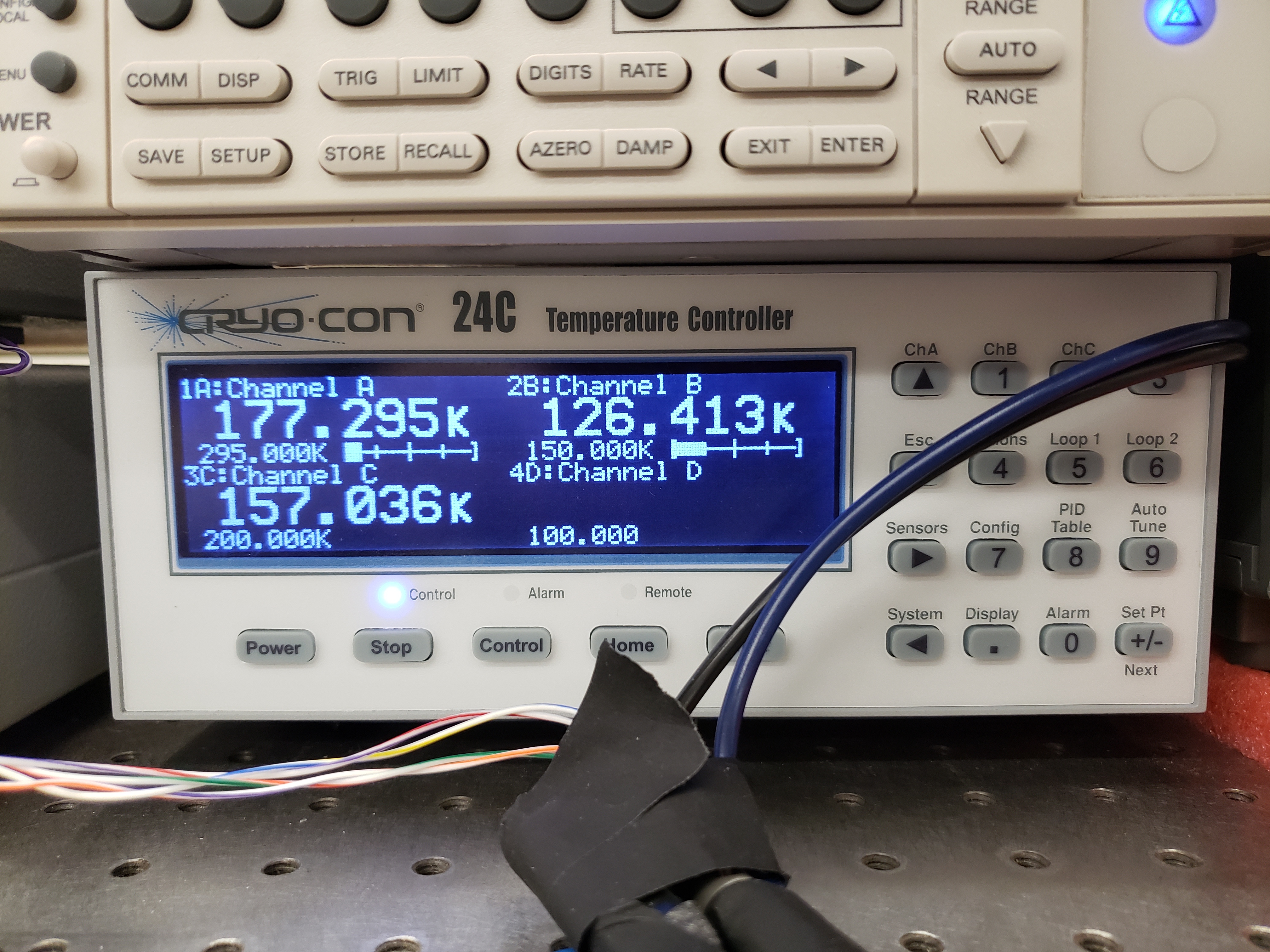
Figure 4 Front panel during normal operation
The dewar contains two 50\(\Omega\) heaters. One heater is mounted on the CCD Stage (Channel A) and one is mounted on the Cold Plate (Channel C). All temperature sensors are 100\(\Omega\) Pt RTDs.
4.1.2 Channel Configuration
Channels can be configured by pressing the button for the appropriate channel (ChA, ChB, ChC). The channel labels are above the buttons. The front panel when configuring Channel A is shown in Figure Figure 5.
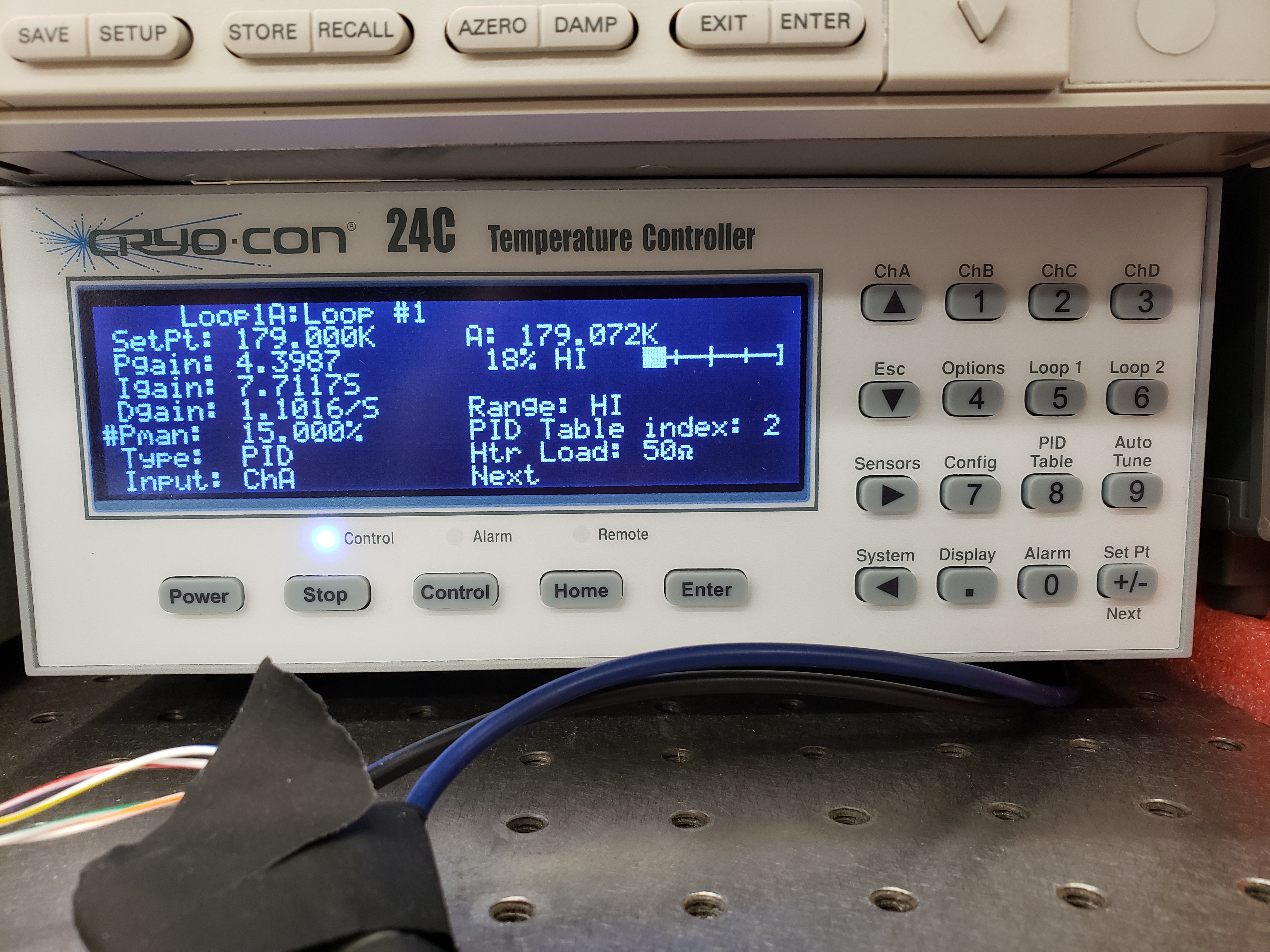
Figure 5 Channel A configuration during normal operation
4.1.3 Alarm Configuration
Once the configuration procedure for a loop has been commenced, both the high alarm and low alarm temperatures should be set. To do so:
- Use the arrow keys to put the cursor (#) next to .
- Set the high alarm temperature in Kelvin (we recommend 308K, 35C) by typing the number and pressing the key
- Set High Enable to Yes by selecting it with the cursor and toggling with the [+/-] key
- The low alarm procedure is identical (set temperature in Kelvin, make sure Low Enable is Yes). We recommend 160K.
- Audible Enable should be set to Yes
- Latched Enable should be set to Yes
- With Latched Enable, a triggered alarm will persist until manually cleared, even if the system returns to a range within the alarms
- To clear a latched alarm, press the key, followed by the key. Note that if the system is in a state that will trigger an alarm (e.g., low temperature), the alarm will immediately re-trigger after clearing.
4.1.4 Configuring Loops
To access the configuration menu for Loop 1, press the key (same for loops 2 and 3). Once in the configuration menu, you can view and change the parameters by moving the cursor to them and pressing the key. The front panel when configuring Loop 1 is shown in Figure 8.4.
Options and their values for normal operations are given below:
- Setpoint is the setpoint of the loop (see Figure below)
- Input is the channel input to the loop (Loop 1 should be ChA,
Loop 2 should be ChC)
- If the loop is in manual mode, channel selection is irrelevant.
- Range sets the current limit for the system. [Low, Medium, High] correspond to current limits of [0.1, 0.316, 1.0] Amps. Loop 1 should be set to High. Loop 2 has 2 available ranges [Low, High] which correspond to [0.22, 0.71] Amps. Loop 2 should be set to High.
- Heater Load informs the controller of the resistance of the heater. For Loop 1, this should be set to 50\(\Omega\). Loop 2 is not configurable and is fixed to 50\(\Omega\).
- Type describes the type of control asserted on the control loop.
- Man manual control
- PID PID control
- Ramp P Temperature ramping using PID
These values can be changed by moving the cursor (#) to the desired parameter, using the key to change the setting, and then pressing the key.
Under normal operating conditions:
- Loop 1 should be set to PID mode with Channel A as input.
- Loop 2 should be left in manual mode.
4.1.4.1 [Optional] Autotuning PID Loops
The Cryocon automatically tunes it the PID loop parameters for a given thermal system and target temperatures. This process needs to be done only when the system or the target temperatures are substantially changed. The front panel when autotuning Loop 1 is shown in Figure 8.4.
The procedure for performing an autotune is as follows:
- Set Type (the loop control) back to Pman.
- Manually change heater value until CCD Stage temperature is near desired temp (we found 15% on Loop 1 and 30% on Loop 2 was about correct for Loop 1 to achieve a temperature around 178K in the lab)
- Press the button, and check these settings:
- Set Autotune to desired loop (Loop 1 for CCD Stage)
- Set Delta P to 2%
- Set Timeout to 600s
- To begin the autotune, scroll to the Go line and press
- If the autotuning succeeds or fails, it will say so after the Go autotune fails, the Delta P and timeout can be tweaked
- If the system succeeds, press on the Save & Exit line
- When you press Save & Exit, the Cryocon will return to PID control and return to the listed set point
The critical items that determine success or failure of the autotuning process are the Delta P and Timeout values. Delta P sets the maximum additional heat load the PID loop is allowed to place on the system. To wit: a Delta P of 2% tells the system that it is allowed to put +/- 2% power across the heater, referenced to its current value. In the case detailed above, that would be roughly 13-17%. The Timeout value sets the length of time the system will use to learn the paramters. Because the ATSSRS has such a large thermal time constant, the value for Timeout should be high – several minutes at least.
5 Start-up/Shut-down
6 Running the Telescope
7 Taking Data
8 Maintenance Procedures
8.1 Pump-down/Cool-down
Take system from atmosphere + room temp to operating vacuum + cryo level
8.2 Warming the Dewar
This procedure details how to warm the ATS from operating temperature to ambient temperature. This process typically takes around 6 hours and dewar temperatures should be monitored throughout the process.
IMPORTANT: The CCD temperature must always remain >3K warmer than the cold stage to prevent condensation onto the CCD. This is especially relevant as the system warms and cools.
After weeks of being cold, the vacuum pressure is around 6-7e-7 Torr. After warming up, but still on the turbopump, it is around 3e-5 Torr. Can get to 6-7e-5 Torr after 20 hours of pumping, assuming it’s not been offline and exposed for very long
Important Concepts
The system requires some hands-on management, in particular during the first phase of the warmup procedure. We have not yet converged on a set-and-forget procedure, so the following is meant as a set of guidelines rather than a concrete recipe. Critical thinking and judicious choices are still required.
There exist 3 sources that can provide heat to the CCD through 2 paths. The first source is the heater located on the CCD Stage. This is the first and most direct path by which the CCD can be warmed. The second path has two contributing heat sources: the heater on the Cold Plate, and the external environment. The Cold Plate is thermally coupled to the CCD Stage by means of a spring-loaded copper disk that presses against the back of the stage.
The voltage sources should be turned off, following the procedure outlined above.
Reduce the heat load on Loop 2 (Channel B, Cold Stage)
- We had Pman for Loop 2 set to 30% during manual operation. We reduced it to 10%.
Ensure the over-temperature disconnect settings are reasonable (typically should be set somewhere around 20C/293K)
- Press [System] key, go to Overtemp config, press [Enter]
- Set OTD Enable to On
- Set OTD Source to ChA
- Set OTD setpoint to 293
Change Loop 1 (Channel A, CCD Stage Heater) Type to Pman (use +/- button)
Decrease Loop 1 heater power
- We changed from 15% to 12%.
Pause, to make sure the system is somewhat stable and that system seems safe. It may be slowely cooling.
Turn off the Polycold using the rocker switch on the compressor.
System will now heat up. Monitor temperatures to make sure Channel A is always >3K warmer than other channels.
Note: Once Polycold is turned off, the dewar interior will begin to thermalize. This may cause the CCD Stage (Channel A) to initially cool as the other Channels warm. As the temperature difference between the channels decreases, the three channels should heat at roughly the same rate, with Channel A staying several degrees warmer than the others.
Note: If the temperature of Channel A comes to close to the other temperatures, the heater power on Channel A can be increased and/or the heater power on Loop 2 can be decreased or turned off entirely.
Note: If the system is heating up too quickly, the power on the heaters should be decreased.
Note: Pressure in the dewar will begin to slowly increase as cryopumping ceases.
Connect and turn on the turbo pump and evacuate the pump line
- Pressure in dewar is a few 10-̂5 torr and/or when the ion pump starts seeing an increased pump current
- Pressure in pump line should be a few 10-̂6 tour before continuing
Open the valve slowly and then turn off the ion pump
Several hours into warmup on 2019/09/11, the pressure in the dewar started to rise, reaching 1E-2 torr. This is due to the charcoal getter releasing water as it heats up. After some time (an hour or two), the pressure dropped rapidly to a few 1E-5. When the system passes the over-temperature setpoint (293K if following the instructions above), the heaters will be disconnected and the overtemp flag will be set. This can be manually reset by pressing the [Control] button, which re-enables the heaters (assuming the system is below the over-temperature disconnect setpoint. The system will thermalize with ambient.
8.3 Venting the Dewar
The process to take the dewar from warm, moderate vacuum (turbo pump only), to atmospheric pressure. Should only be done in a clean area to avoid dust contamination in the dewar.
- Warm the system, as described above.
- Power off all electronics
- Put on a grounding strap and ground yourself.
- Unplug ion pump from power supply.
- Unplug the fans.
- Disconnect temperature monitoring and control wires (one on side flange, one on back plate).
- Disconnect Polycold gas lines
- Be careful not to torque the Cold Head coupling fixture (use 2 wrenches).
- CAP THE GAS LINES AND GAS INPUTS IMMEDIATELY AFTER DISCONNECTING.
- Prepare to Disconnect dewar from turbopump
- Close the dewar valve. The valve should be firmly shut, but do not over-tighten the valve.
- Turn off turbo power using the button on the front panel of the station.
- Wait for turbo to spin down. Do not open the relief valve until the turbo has completely spun down. Failure to do so may result in destruction of the pump.
- Slowly open relief valve on turbopump (small black knob on rear of turbo housing) until pressure hits ambient (~750 Torr in Tucson, will be less on the mountain).
- Follow best practices for vacuum equipment (i.e., try not to let dust/oil/grease/etc. enter the pump hose, use nitrile gloves to handle o-rings and vacuum surfaces).
- Detach and seal both the dewar valve and pump hose with a KF40 blank flange. This is especially important to avoid dust contamination of both the dewar and turbo pump.
8.4 Opening the Dewar
Only under extreme circumstances